-
Okay, I have a Basic loader with M/L code that enables a screen buffer and has a handy relocatable M/L routine at
$C000that copies 1024 bytes. Bits 4 - 7 of$D018control which part of memory is used to display the screen. Now I have all I need for moving a block of characters in C64 Basic, right? 👨💻 -
Make room for a screen buffer in C64 Basic
In my previous post in which I moved a box across the screen with a Basic program, I wanted to use a screen buffer. The default screen location starts in memory at
$0400(1024 decimal), and we can move the screen in units of 1024 bytes. The next location would be$0800(2048 decimal), which is where Basic text lives. Luckily we can move the start of Basic up with apokeat location 44, but we also have to move the bytes of the Basic text to the new location, or you’d get a jibberish Basic text. The most obvious location is$0c01(3097 decimal), and it makes sense to do this outside of Basic, with the raw power of the 6510 CPU.The machine language (M/L) program
enablebufferdoes just that. Here’s the source code listing. It has some Basic code to run the M/L code and relocate the start of Basic text. The M/L code is a bit more complicated than it needed to be, but I like some headroom in case I want to include more Basic text in front of the M/L code or put some M/L code in a convenient location, so we cansysorusr()to it. The code should be able to copy Basic text in front of the M/L code, no matter how big it would grow.; enablebuffer.asm ; ; Move the start of basic from $0801 to $0c01 ; ; Now both 1024 - 2023 and 2048 - 3047 ; can be used as screen memory. ; This makes it possible to use a screen buffer ; in Basic. PROCESSOR 6502 ORG $0801 ; Basic text in front of ML code ; 10 SYSXXXX:POKE44,12:CLR BASIC1: HEX 14 08 0a 00 9e .dc sys_address ; replaces the "XXXX" BASIC2: HEX 3a 97 34 34 2c 31 32 3a 9c 00 00 00 sys_address: eqm (start_ML)d ; start of ML code start_ML: vect1: eqm $02 vect2: eqm $04 BASstart: eqm $2B LDA BASstart+1 CMP #$08 ; is start of basic at $0801 ? BNE exit ; no, then exit ; set up copy process ; copy $0801 to $0C01 until the end of file ; copy start at the end towards the beginning CLC LDA #exit STA vect1+1 ADC #$04 ; move 1024 positions higher in memory STA vect2+1 LDY #$00 loop1: LDA vect1+1 ; copy in blocks of 256 bytes CMP #$08 ; less than 256 bytes to copy? BEQ loop2 ; yes, then loop2 instead loop1a: LDA (vect1),Y ; fast copy 256 bytes STA (vect2),Y DEY BNE loop1a DEC vect1 ; next 256 byte DEC vect2 BNE loop1 DEC vect1+1 DEC vect2+1 BNE loop1 loop2: LDA (vect1),Y ; copy remainder of bytes STA (vect2),Y ; between 1 and 255 DEC vect1 DEC vect2 BNE loop2b DEC vect1+1 DEC vect2+1 loop2b: LDA vect1+1 CMP #$07 BNE loop2 exit: RTS We can load the program as an ordinary Basic program and then run it.
After that we can
newthe Basic program and start writing a new Basic program, at location$0C01instead of the default$0801! Of course, the M/L code will be overwritten by that new Basic program, but that’s okay, since we no longer need it at that point. -
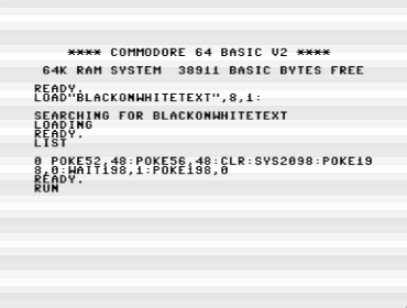
With all the blogging I do daily, I wanted to automate correct capitalization. I reworked an shortcut that no longer worked to a working state. Select text, share, pick one, paste.
- all lower case
- UPPER CASE
- Title Case in Case You Want It
- Capitalize A Okay
- Sentence. After each. Sentence.
-
Moving a box across the text screen in C64 Basic
I was wondering how to move a collection of characters (e.g. a box) across a Commodore 64 text screen. It’s rather easy to do this destructively. In Basic, I wrote something that horizontally moves a 3-by-3 character rectangle constructed out of PETSCII characters.
10 rem ***
11 rem *** setup
12 rem ***
20 restore:read w,h:for i=0 to w*h-1
30 read a(i):next i
40 data 3,3
50 data 112,64,110,93,32,93,109,64,125
60 te=200
100 rem ***
101 rem *** main loop
102 rem ***
110 os=0
120 for p=1024+12*40top+40-w
130 gosub 200:gosub 300:next p
140 os=w-1
150 for p=1024+13*40-w to p-39+w step-1
160 gosub 200:gosub 300:next p
170 goto 100
199 end
200 rem ***
201 rem *** draw a box
202 rem ***
210 for x=0 to w-1:for y=0 to h-1
220 poke p+y*40+x,a(y*w+x)
230 nexty:nextx:fort=0tote:nextt:return
300 rem ***
301 rem *** clear column
302 rem ***
310 for y=0toh-1:poke p+y*40+os,32:next
320 return
The program has to do some clean-up after it has drawn a box with the subroutine
draw a box. It fills the box’s trailing text column with space characters (screen code 32). For instance, if the box moves to the right and the box has been drawn in its current position, the left-most text column of that box has to be “cleared” (filled with spaces). Otherwise it will leave behind box characters when the next position of the box is drawn—one position to the right. Themain loopuses the variableos(offset) to determine which text column should be filled with spaces, using the same subroutineclear columnwhen moving the text box to the left or to the right.It’s all very limited in what this program can do. It can move the box either one character position to the right or the same to the left, nothing more.
For a more sophisticated
draw a boxsubroutine, it has to know where it was before:- restore the original content of the previous position (if any)
- read the current content where the box will appear and store it for later
- draw the box onto its position on the text screen
We can do this in Basic as well, even though it’s rather slow and has clear visual artifacts. Here’s the code for the same 3 by 3 text box, now jumping to arbitrary positions on the screen, while keeping the screen intact.
10 rem ***
11 rem *** setup
12 rem ***
20 restore:read w,h:for i=0 to w*h-1
30 read a(i):next i
40 data 3,3
50 data 112,64,110,93,32,93,109,64,125
60 te=200
70 first = (1 = 1)
100 rem ***
101 rem *** main loop
102 rem ***
110 x=int(rnd(ti)*(40-w))
120 y=int(rnd(ti)*(25-h))
130 gosub 200
140 goto 100
199 end
200 rem ***
201 rem *** draw a box
202 rem ***
210 rem *** restore any orig'l content
211 rem ***
220 if first then first=(1=0):goto 300
230 for xx =0 to w-1:for yy=0 to h-1
240 poke p+yy*40+xx,a1(yy*w+xx)
250 nextyy:nextxx
300 rem ***
301 rem *** read current text content
302 rem ***
310 p=1024+40*y+x
320 for xx=0 to w-1:for yy=0 to h-1
330 a1(xx+yy*w)=peek(p+xx+yy*40):
340 nextyy:nextxx
400 rem ***
401 rem *** put box on screen
402 rem ***
410 for xx=0 to w-1:for yy=0 to h-1
420 poke p+yy*40+xx,a(yy*w+xx)
440 nextyy:nextxx
450 for t=0 to te:next
460 return
The long wait loop (which makes the program perform so slow) is so that you can spot the random 3-by-3 box, while also making the artifacts less noticeable. You can see the box long enough, so it disappearing from screen will feel less jarring. A better solution than waiting a while would be to use a screen buffer to do the drawing and switch screen buffers when all the drawing is done for the new position of the box.
I guess that would require some machine language I have yet to write.
-
I wondered if a sprite rendered as a text character would make sense. It would have to move to one of the 1000 positions on a text screen of 25 lines and 40 columns in a C64. The character is 2 by 2 text characters, has 3 walking poses, and two extra text characters for the SFX. It could work 👨💻
-
I would prefer owning a Mac, but I simply can’t rationalize the “Apple tax.” I used to be Mac or Die. A computer is more like a way to access the Internet nowadays, anyway 👨💻👾
-
It’s all very technical, this Commodore 64 multicolor mode. I made a special 2x1 grid in my iPad pixel editor to help me, but still I need to check in an actual multicolor editor if I made a mistake. Anyway, I’m improving as a C64 pixel artist, and that’s very cool 👨💻
-
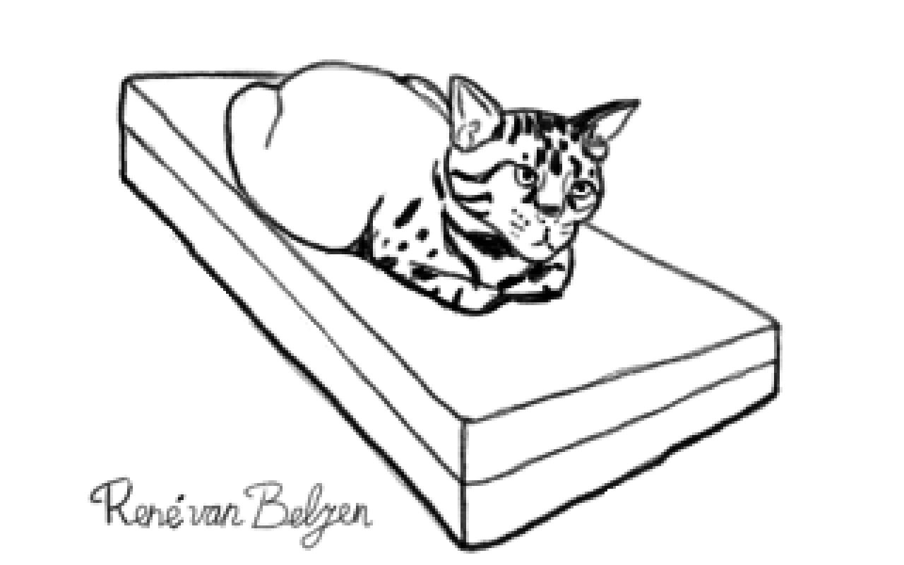
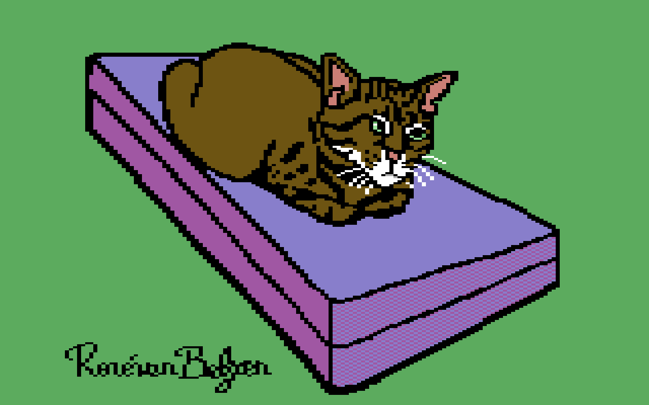
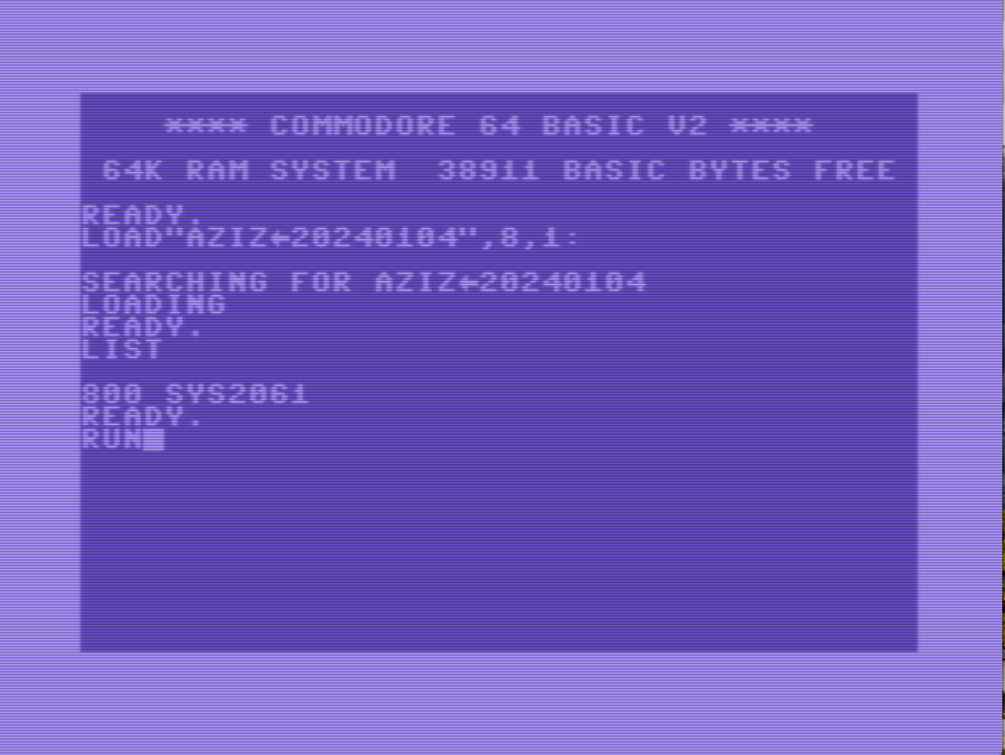
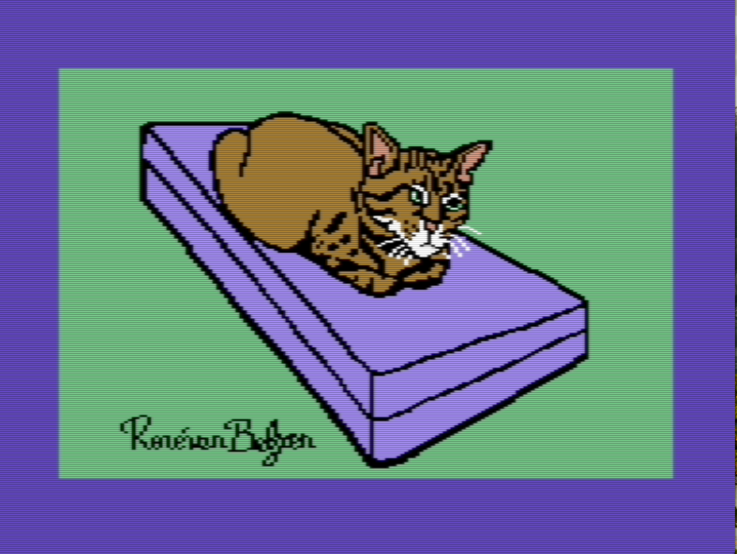
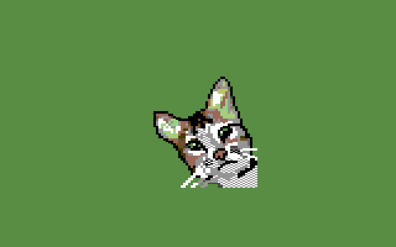
Creating something colorful that can be displayed on a Commodore 64 by loading and running a file involved a lot of (impossible to automate) creative steps. It took me around 4 hours for this simple drawing of my cat Aziz. 👨💻
-
I found an image editor that is able to draw Commodore 64 multicolor images. It can load PNG images, so I could draw on my iPad and color in this Java app on my Raspberry Pi-400. Yay!
I’m still learning, though. Also found a SID tracker to compose music on the C64, and my musical knowledge is meh.
-
Basic music theory—the musical interval
Realizing how little to nothing I know about music theory, I started watching videos on the subject recommended to me by YouTube. Apart from that those videos aren’t really vetted, I don’t know how useful those are, even if they’re accurate. So there’s my caveat to you, the reader.
Today I researched the musical interval, i.e. the ratio in frequency value between musical notes.
In Why Does Music Only Use 12 Different Notes? presenter David Bennett explains how musical notes work in popular and classical music, which most of us listen to on a daily basis.
There are the following 12 notes (semitones) in an octave (using letters, while in some countries other notations are used, like do-re-mi):
- C
- C#
- D
- D#
- E
- F
- F#
- G
- G#
- A
- A#
- B
When a note has a frequency twice as high as another note, the distance (interval) between them is called an octave. Playing two notes an octave apart sounds pleasing (consonant) to our human ears.
Inside an octave there are 12 notes. Playing two of those notes together gives a certain mood (how humans perceive the combination of notes, pleasing or less pleasing). The first of those 12 notes is called the root. Playing the root and the same note an octave higher gives us the most consonant combination of notes.
On a scale from most consonant to most dissonant, there are twelve musical intervals (between brackets is the frequency ratio between both notes in the interval). The intervals numbered 1 - 7 in this list are considered consonant in Western music, 8 and higher dissonant.
- Octave, aka 8ve, (2:1)
- Perfect 5th, aka P5 (3:2)
- Perfect 4th, aka P4 (4:3)
- Major 3rd, aka M3 (5:4)
- minor 6th, aka m6 (8:5)
- minor 3rd, aka m3 (6:5)
- Major 6th, aka M6 (5:3)
- Major 2nd, aka M2 (9:8)
- minor 7th, aka m7 (9:5)
- minor 2nd, aka m2 (16:15)
- Major 7th, aka M7 (15:8)
- Tritone (7:5)
Below that, sounding even less pleasant, there are quarter-tones, and even further divided intervals, that sound even more unpleasant.
Ordered on frequency (how they appear on a piano keyboard, using both white and black keys):
[root] [m2] [M2] [m3] [M3] [P4] [Tritone] [P5] [m6] [M6] [m7] [M7] [8ve]With 12 notes in an octave we have a limited set of frequencies. It is a practical compromise, really, limited to only the most useful musical intervals, excluding others. However, this compromise is still not enough. With the ratios mentioned above, we can only play in a fixed key (root note). If we want to transpose a piece of music to a different key with the ratios kept intact, the musical intervals sound all weird. This is because this theoretical just intonation doesn’t allow for transposition. To fix it, so we can play in any key we want, the intervals must be changed. This slight alterations in musical intervals is called temperament (tempering the intervals so music can be played in arbitrary keys, not just one single key).
There have been several temperaments over the millenia and ages. The system we use today is called 12 Tone Equal Temperament. Each semitone is a factor of the 12th root of two higher than the previous semitone.
Here are the tempered values of the intervals. They are very close to their just intonation, between brackets:
- m2 1.0595 (1.0667)
- M2 1.1225 (1.1250)
- m3 1.2892 (1.2000)
- M3 1.2599 (1.2500)
- P4 1.3348 (1.3333)
- Tritone 1.4142 (1.4000)
- P5 1.4983 (1.5000)
- m6 1.5874 (1.6000)
- M6 1.6818 (1.6667)
- m7 1.7818 (1,8000)
- M7 1.8877 (1.8750)
- 8ve 2.0000 (2.0000)
Except for the octave, these intervals are slightly out of tune compared to the ideal, but not enough to be noticeable, especially the perfect 4th and 5th are extremely close in value to a just intonation. Using this temperament musicians can play in any key without the music sounding strange. Anyway, the music most of us listen to (Western music) has been already in 12 tone equal temperament for hundreds of years. Most of us (including myself) probably don’t know any better.
It’s a small, yet important part of music theory.
-
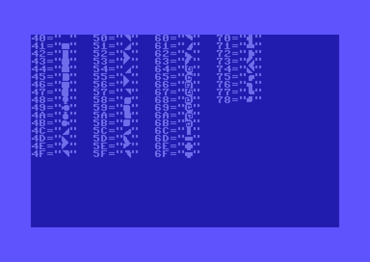
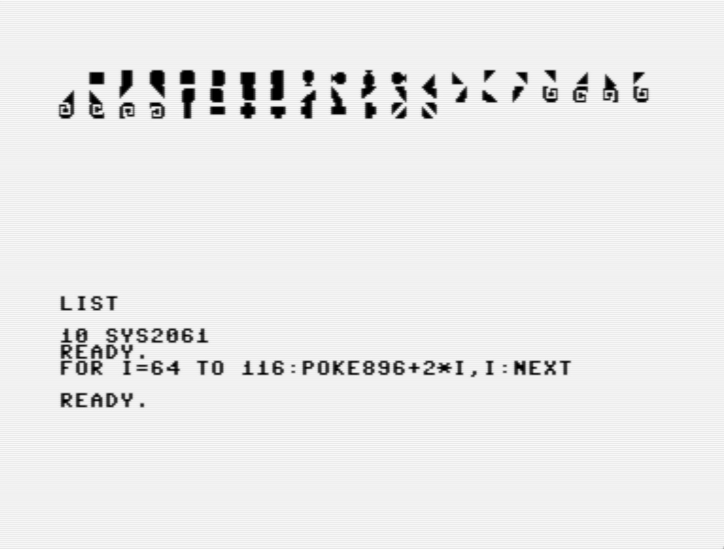
I realized I needed four extra characters to be able to create lines that are 4 pixels wide. In the 6-pixel wide versions I already had them ($59 - $5B), rounding corners. So I added them to my existing modified character set, at $75 - $78.
Tools: PETSCII editor, VICE.
👨💻 day 2/366 days of coding
-
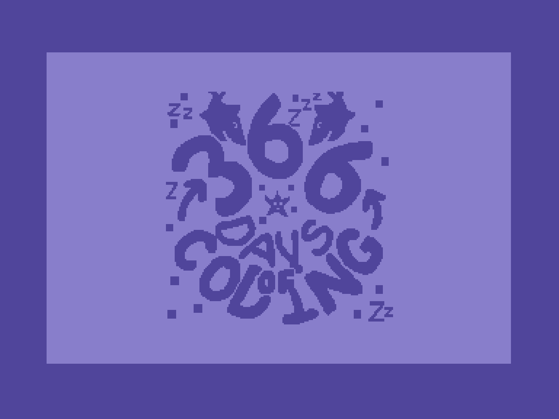
It’s day one of a year long self-challenge to code a video game for the Commodore 64. It won’t be all spent behind a keyboard and monitor. There’s a lot of study ahead, reading books and articles, playing retro-games, etc. Also making pixel art and chiptunes. It’ll be a blast 🥳 👨💻
-
My retro-computer∗ powered best wishes from the Netherlands!
May all your best wishes for 2024 come true.
👨💻

∗ (V.I.C.E. actually, and a little after effect with my iPad)
-
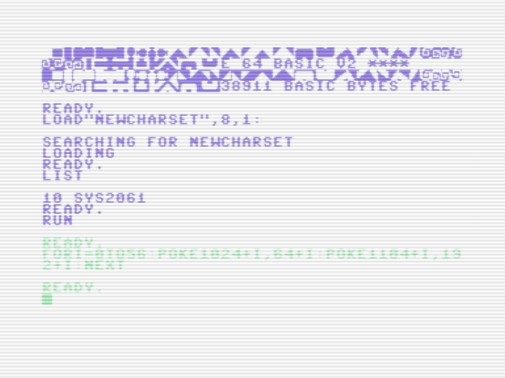
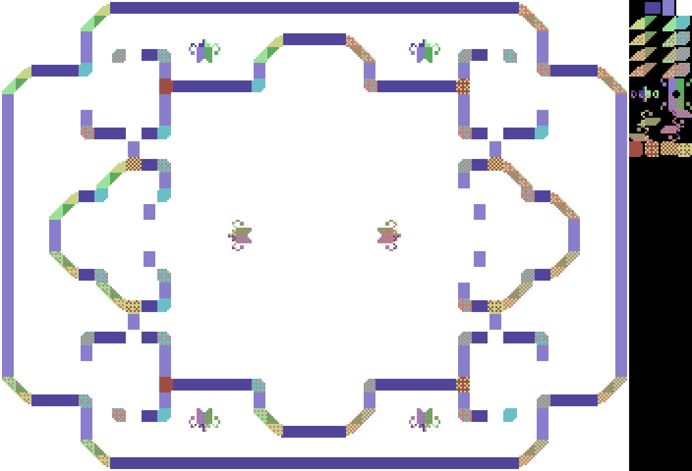
Took some effort, yet I have my character set of programmable characters to draw a design I’ve been working on lately. I wrote a Basic loader, which when run puts the character set in memory, so I can be used. Still lots to do, though. I’ll write a longer piece about it in the New Year. 👨💻
-
Second (partial) attempt at a a 2-color bitmap image on a C64 as a collection of characters (8-by-8 pixels tiles, still only 39). This is very laborious—if done by hand. I had to change the original rather drastically, and reuse tiles with care. There’s still a good resemblance, of course. 👨💻
-
I wonder if it’s possible to render this as 8 by 8 tiles, and if so, how to do it. 👨💻

-
I made start with software sprites using programmable characters on a Commodore 64. For now, there are just programmable characters; there’s no background, nor a software sprite that should move over the background in one of the 1000 possible positions on a 25 rows by 40 columns text screen.
-
How to draw software sprites
While in the previous article I was only philosophizing, in this one, I’m getting somewhat less theoretical. It’s still a ways away from having working code, though.
I found an answer on the Retrocomputing Stackexchange site, explaining how software sprites “work”. In my own words:
Sprites are rectangles of image data that are put in video memory, so the video processor can display them on a video screen. Sprites always need one of the colors to be transparent (invisible). In a two-color display that usually is black (0), while the visible color is non-black (1). The invisible color could be considered the background color, the visible color the foreground color. However, with a background drawn on screen, things can get confusing.
To enable mixing of sprite images with the background image, for every sprite image there should be a mask to punch a whole into the background. The mask contains 0s where the sprite image is visible; 1s where the sprite image is transparent. It makes sense to precompute mask data for efficiency.
Sprite data is drawn on top of image data. First, the background is masked out where the sprite will appear, resulting in a “hole” in the background. Second, this hole is filled with sprite data. Of course, if the sprite was moved, the original background image of that previous location should be restored too.
On older PCs (read: in certain display modes) colors are planar, which means that each color is stored in its own block of memory, instead of combined into a single memory block (one or more bytes of color information per pixel). Each color plane has to be processed first by punching a hole with the same mask and then filling the hole with sprite image data, specific for that color.
The (generic) algorithm for drawing sprites is as follows:
- erase the previous position, if any, by copying the original background at the previous location
- establish the address of the rectangle in video memory where the sprite should appear
- apply AND with the mask on this rectangle to “cut” data behind the mask; now there is a hole in the background where the mask is
- apply OR with the sprite image data to insert it into the background image; OR will only draw inside the cut mask
On the C64, things are quite different if bitmap graphics is to be ignored (too slow in most cases). In two-color (monochrome) character display, there are 1000 character positions (25 lines of 40 characters). The characters can be programmed by changing their image data (8 rows of 8 columns of pixels). In character generator memory, blocks of 8 bytes (8 by 8 pixels) are stored for each of the 256 characters that are in a character set. To display a character, its code is stored in screen memory, depending on the character’s location (column and row) on the video screen.
Let’s imagine a single 8 by 8 character (organized as 8 rows of 8 bits, 64 bits in total). Since the characters don’t represent text, but rather images, it’s probably better to refer to them with the more generic term “glyph”. A glyph can be a character, but also an image, e.g. a sprite.
To remove a sprite from the previous position, the previous glyph code that represented the background in that position is put back in screen memory. The background glyph code should be stored somewhere separately if it isn’t possible to determine that code from its position alone.
To put a sprite in its new position, some bit manipulation has to be done, combining the original image data of the background glyph with that of the sprite and store the result into image data for the glyph that displays a sprite-on-background.
The data structure that contains a sprite could look something like this:
- memory address in screen memory (2 bytes)
- background glyph code (1 byte)
- sprite-on-background glyph code (1 byte)
- sprite image data (8 bytes)
- sprite mask image data (8 bytes)
That is 20 bytes in total for displaying a single 8 by 8 square of pixels. That could be 8 bytes less if the sprite mask image data is computed on the fly.
From the steps above in the general case, the C64-specific steps would look like as follows:
- if the sprite was already being displayed, write the background glyph code into the memory address in screen memory
- calculate the current memory address in screen memory, based on the given sprite location
- store the glyph code in the memory address in screen memory in the background glyph code
- AND every of the 8 bytes of mask data with the corresponding bytes of background image data, as determined by the background glyph code and store the result in the 8 bytes of image data for the glyph that displays sprite-on-background
- OR every of the 8 bytes of sprite image data with the corresponding 8 bytes of the sprite-on-background image; store the result back into the sprite-on-background image
- write the sprite-on-background glyph into the current memory address in screen memory
That is a lot of overhead and storage space for sprite the size of a single character of text. If the sprite needs to be able to be moved left and right, up and down, with the resolution of a single pixel, things can get even more complicated and require even more resources (instruction cycles and storage space). It’s doubtful if this kind of accurate positioning is sensible, if one could use hardware sprites for pixel-wise movement instead.
I’m curious how this could be coded, and then recoded for efficiency (storage-wise and/or instruction-cycle-wise). I’m sure it depends on what is needed for the game.
To make it more interesting for video games, one would like to introduce colors, like in multi-color character mode, and bigger sprites. I might not get to this, because monochrome character mode seems daunting enough for me.
-
Philosophizing about software sprites
While reading through some articles about hardware sprites, sometimes called movable object blocks (MOBs), I realized that the C64 is probably too slow to move software driven sprites. In 1/60 s at ± 1.02 Mhz there are 17000 instruction cycles for an interrupt, or (
17000 / 4 =) 4250 average instructions per interrupt cycle.A typical copy operation is with zero page indexed addressing in a loop requires 14 instruction cycles per copied byte. Add to this a bit shift in a buffer (add another 4 cycles), and an area of 32 by 23 pixels to hold a 24 by 21 pixel MOB, then a back of the envelope calculation gives us (
4 x 23 x 18 =) 1656 instruction cycles per pixel shifting MOB, at 60 fps. With nothing else to do, that would give us (17000 / 1656 =) 10 MOBs at most.If the Kernal is supposed to do something, like being able to run Basic, then it’s probably feasible to maintain 3 MOBs at most.
Another calculation. What if one wanted to fill a whole screen, all 1000 bytes at 14 instruction cycles per byte? With the interrupt disabled, that would make a refresh cycle possible of at most 1/7th of a second, which is clearly noticeable. It makes sense in that case to use a frame buffer, and switch buffers after a buffer has been updated. This would enable slowly animating backgrounds, in other words, choppy animation, which could be interesting in some cases. There wouldn’t be any redrawing of the screen, breaking suspension of disbelief in most players.
Of course, it’s possible to rewrite only a part of the buffer, so the frame rate can be increased. Using the estimated 3 MOBs per 1/60 s. That is (
(4 MOBs of 23 rows of 4 bytes) / (40 bytes per line) =) 9 lines per 1/60 s, or around (9 / 25 ≈) ⅓ of the screen which can be believably animated using a frame buffer. This needn’t be a contiguous areas. Disparate parts of the screen could be animated, at some instruction cycle cost to update zero page pointers to new values.I should emphasize, this is all theoretical (philosophical?) and for 2-color MOBs. With multi-colored MOBs more bytes need to be updated, reducing the frame rate by at least 50 percent. The “claims” above have to be proven by code first.

It was fun dreaming about such an endeavor, and see what the possible limits would be. For snappy code, one should really disable the Kernal interrupt routine, and use one’s own instead. I suppose this is why most video games require a reset to return to Basic. If Basic has to coexist, it will limit what kind of games can be played. Fast moving action-based games are probably not among those. In that case, you’re probably already committed to using hardware sprites.
-
I have a very unoptimized way to fill a rectangle on a C64 video screen with characters, as in a MOB (movable object) instead of a hardware sprite. It’s around 25 times faster than using Basic, and has “frame rate” of around 12 fps on a 50 Hz monitor. I’m sure it can be much faster. 👨💻